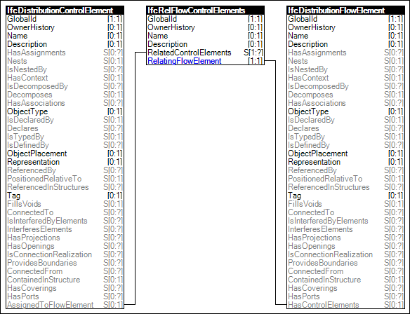
Figure 37 — Control Flow
Control elements (such as sensors) that monitor or control behavior of flow elements (such as valves) use this relationship to indicate control flow logical behavior.
Figure 37 illustrates an instance diagram.
 |
Figure 37 — Control Flow |
<?xml version="1.0"?>

<ConceptTemplate xmlns:xsi="http://www.w3.org/2001/XMLSchema-instance" xmlns:xsd="http://www.w3.org/2001/XMLSchema" uuid="d1d8208b-51e5-4a8f-92ba-e3a2ea2bcb9c" name="Control Flow" applicableSchema="IFC4" applicableEntity="IfcDistributionControlElement">

  <Rules>

    <AttributeRule AttributeName="AssignedToFlowElement">

      <EntityRules>

        <EntityRule EntityName="IfcRelFlowControlElements">

          <AttributeRules>

            <AttributeRule RuleID="Type" AttributeName="RelatingFlowElement">

              <EntityRules>

                <EntityRule EntityName="IfcDistributionFlowElement" />

              </EntityRules>

            </AttributeRule>

          </AttributeRules>

        </EntityRule>

      </EntityRules>

    </AttributeRule>

  </Rules>

</ConceptTemplate>