NSDT工具推荐: Three.js AI纹理开发包 - YOLO合成数据生成器 - GLTF/GLB在线编辑 - 3D模型格式在线转换 - 可编程3D场景编辑器 - REVIT导出3D模型插件 - 3D模型语义搜索引擎 - AI模型在线查看 - Three.js虚拟轴心开发包 - 3D模型在线减面 - STL模型在线切割 - 3D道路快速建模
本文将介绍一种非常有吸引力的机器学习训练数据的替代方案,用于为给定的特定应用程序收集数据。 无论应用程序类型如何,这篇博文都旨在向读者展示使用 Blender 等开源资源生成合成数据(Synthetic Data)的潜力。
事实上,对于现实生活中的数据而言,在短时间内收集数据并对其进行标记的需求尚未得到完全解决。 这就是为什么,为了解决这个问题,我们必须转向合成数据生成,通过适量的代码,它可以提供稍后训练深度学习模型所需的标签和特征。
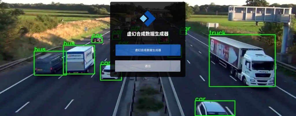
在本例中,我们专注于对象识别问题,并使用 Blender 及其脚本功能生成数据。如果你喜欢虚幻引擎的逼真效果,可以使用UnrealSynth这个基于UE5开发的YOLO合成数据生成器,非常方便:
1、项目概况
对于这个项目,我们将生成数据来识别下图中所示的木制玩具。 为了做到这一点,我们将创建一种算法,以与图片中相同的配置拍摄所有对象的照片,并输出与每个图像中每个对象的位置的边界框相对应的标签。

我们希望识别的类如下:
    Pink flower
    Blue square
    Green star
    Yellow hexagon
    Orange lozenge
    Pink oval
    Blue rectangle
    Green circle
    Orange triangle
上述算法将在渲染软件Blender中用Python实现。 Blender 是一款开源软件,用于从动画到产品设计等多种渲染应用程序。 该软件将允许创建上面看到的对象的真实渲染,同时也允许我们访问每个对象的位置,这是完成标记的关键功能。
本文的 Blender 文件、整个代码和所有必要的资源都可以在这里下载。
2、Blender场景设置
无论你想要识别哪个对象,为了生成合成数据来训练其识别器,我们都必须在 Blender 中表示这个或这些对象。 因此,我们必须创建和设置一个与实际场景最相似的场景,我们通常会在其中找到我们想要识别的对象。
为了解释如何做到这一点,在本节中,我们将引导读者完成设置与自动生成数据的脚本兼容的场景所需的主要步骤。
2.1 CAD模型导入
第一步包括将我们想要识别的对象导入(或创建)到 Blender 中。 在我们的例子中,我们决定在 Catia V5 中创建 CAD 模型,然后将其导入为 .stl。 也可以在 Blender 中从头开始创建模型,但是,由于我们更熟悉 Catia,因此我们决定在该软件上执行此操作。

然后我们继续打开 Blender 开始导入我们想要识别的每个 .stl 对象。 我们单击“文件”窗口,然后单击“导入”,最后选择“Stl(.stl)”选项,以导入之前从 Catia V5 导出的模型。

在完成 STL 导入之前,我们必须指定比例为 0.001,因为 Blender 的工作单位为米,而 Catia 的工作单位为毫米。 这使我们模型的单位缩放到 Blender 参考系统,因此在后期阶段,与导入的模型相比,相机具有成比例的尺寸。

将每个对象导入 Blender 环境后,请确保创建一个平面来描绘场景的表面。 另外,请确保命名“场景集合”菜单中的每个对象,这些对象可以在下图中的右侧面板中看到。 确保这些名称易于书写、简短,并且如果名称包含两个单词,则用下划线连接。

2.2 场景定义
导入模型后,我们将继续定义整个场景,以使其看起来最真实。 场景越真实,我们的训练数据就越好,我们的算法就越能识别我们训练它检测的现实生活中的物体。
因此,我们首先通过选择每个对象并进入右侧面板中的“材质”选项来定义每个对象的材质,如下所示。 调整对象外观的三个关键参数是基色、镜面反射和粗糙度。 需要调整后两者来定义物体是吸收还是反射光,是有光泽的还是无光泽的。

此外,如果需要,可以将纹理添加到场景中的对象。 这些纹理可以从图像中导入,并从图像中施加基色。 对于我们的项目,纹理被添加到地板和容纳物体的平台上。

接下来,定义灯光,可以通过复制并粘贴第一个灯光来创建第二个灯光,该灯光是在 Blender 场景启动时自动创建的。 至于对象,请确保为这些灯光分配名称,例如 light1 和 light2,以便你在进入脚本部分后可以在代码中轻松调用它们。
这两个灯光最重要的参数是“功率”参数,一旦我们进入脚本部分,它将使我们能够调整灯光的强度。 如下图,右下角,我们可以看到“灯光属性”面板打开,功率参数为16W。

定义了所有材质并添加了适合目的的灯光后,我们可以通过单击下图中用绿色圈出的右上角按钮来继续可视化渲染。 这允许我们在渲染模式下访问视口着色。

现在场景搭建完毕!
2.3 相机设置
设置 Blender 场景以开始编写脚本的最后一步是设置相机! 这一步实际上至关重要,因为我们需要能够通过脚本轻松控制相机,使其移动并拍照。 我们决定让相机围绕物体旋转,从各个角度拍照。
然而,如果我们考虑相机设置移动的立方空间 (x,y,z),这种运动就不那么明显了。 这意味着设置定义描述对象周围球形运动的 (x,y,z) 点列表会太复杂。 因此,为了简化这项任务,我们决定创建一个固定在场景中心的轴,相机移动时将遵循该轴。 这意味着当轴在中心旋转时,相机将随之旋转。 想象一下,将你的肘部放在桌子上并移动你的拳头,拳头围绕你的肘部旋转。 现在想象一下,肘部是轴,拳头是相机,相机绕轴旋转。
因此,我们创建一个轴并将其放置在场景的中心,如下所示。

现在,为了使相机的移动服从轴的移动,我们按住 Shift 键并首先选择相机,然后选择轴。 一旦它们都被选择,我们点击 Ctr + P 并选择对象(保持变换)。 这将使该轴成为相机的父轴。

你可以继续测试这是否有效,方法是进入相机视图,选择轴并进入下图中以绿色突出显示的变换窗口,然后更改轴的旋转坐标。 当轴旋转坐标改变时,你会看到相机绕物体旋转。

3、Blender Python脚本
现在完整的场景已经设置完毕,我们可以开始编写Python脚本了。 此 Blender 功能将使我们能够自动生成渲染,以便制作数以万计的图片和标签,这些图片和标签将用作我们的对象识别算法的训练数据。 这是非常强大的,因为这意味着如果我们有一个足够真实的 Blender 场景,我们可以在大约两天内生成多达 20000 个图像和标签(这个时间将根据你自己机器的 GPU 的容量而变化)。
可以通过单击下图中橙色下划线的脚本窗口来访问此脚本功能。 通过单击此窗口,我们将出现三个主要元素:以黄色显示的 Blender 控制台、以橙色显示的脚本环境以及以绿色显示的命令跟踪器。

命令跟踪器允许你跟踪在 Blender 环境中修改特定参数时正在使用的实际脚本命令。 例如,在下图中我修改了Axis的位置。

脚本环境允许你导入和保存以前创建的 Python 脚本。 脚本环境中的脚本将保存到你选择的外部位置。 此外,当脚本准备就绪时,你可以通过单击“运行脚本”按钮来运行它

最后,一旦脚本准备好运行,请转到“窗口/切换系统控制台”以访问显示代码输出的控制台。 下图可以更好地体现这一点。

4、Blender 控制台简介
Blender 控制台允许用户使用 Pyhton 语言将算法输入到 Blender 环境中。 当自动生成数据时,它非常有用。 在这里,我们解释了用于生成数据的不同步骤。
4.1 访问场景信息
在下面的代码中,你可以看到如何访问场景信息。 bpy.data.scenes 是在 Blender 中打开的所有场景的集合。 在我们的例子中,只创建了一个场景。 你可以使用命令 bpy.data.scenes[0] 或 bpy.data.scenes['Scene'] 访问它。
>>> bpy.data
<bpy_struct, BlendData at 0x000001C251997458>

>>> bpy.data.scenes
<bpy_collection[1], BlendDataScenes>

>>> bpy.data.scenes[0]
bpy.data.scenes['Scene']

>>> bpy.data.scenes[1]
Traceback (most recent call last):
  File "<blender_console>", line 1, in <module>
IndexError: bpy_prop_collection[index]: index 1 out of range, size 1

>>> scene = bpy.data.scenes[0]
>>> scene
bpy.data.scenes['Scene']
4.2 访问对象信息
我们还需要访问对象信息。 事实上,我们将修改几个对象参数,例如灯光的亮度和相机的位置。 bpy.data.objects 是场景中所有对象的集合。 在我们的例子中,我们有 15 个不同的对象。 因此,你可以通过两种不同的方式调用对象:
- 使用语法
bpy.data.objects[x],其中 x 是 0 到 15 之间的数字,表示场景中对象的数量 - 或者使用语法
_bpy.data.objects['Name'],其中Name是你要调用的对象的名称。
然后,你可以将刚刚调用的对象存储在变量中以供进一步使用。
>>> bpy.data.objects
<bpy_collection[15], BlendDataObjects>

>>> bpy.data.objects[0]
bpy.data.objects['Camera']

>>> camera = bpy.data.objects['Camera']
>>> bpy.data.objects[1]
bpy.data.objects['Carre bleu']

>>> bpy.data.objects[2]
bpy.data.objects['Conteneur coupe']

>>> bpy.data.objects[3]
bpy.data.objects['Empty']

>>> axe = bpy.data.objects[3]
>>> axe
bpy.data.objects['Empty']

>>> camera
bpy.data.objects['Camera']

>>> carre_bleu = bpy.data.objects['Carre bleu']
>>> carre_bleu
bpy.data.objects['Carre bleu']

>>> bpy.data.objects['Light']
bpy.data.objects['Light']

>>> light1 = bpy.data.objects['Light']
>>> light2 = bpy.data.objects['Light2']
>>> light1
bpy.data.objects['Light']

>>> light2
bpy.data.objects['Light2']
4.3 修改对象信息
对于每个对象,可以在场景编辑器中修改它们的信息(位置、位置等)。 在下图中,可以看到如何修改对象的旋转。 了解对象参数的实用性对于能够创建适当的算法非常重要。 你可以看到,当修改参数时,其值也会在控制台中更新。

我们现在可以使用以下代码行修改控制台中的不同参数:
>>> axe.rotation_euler = (0,0,0)
>>> camera.location = (0,0,0.5)
>>> light1.data.energy = 50
>>> light2.data.energy = 0
light1.data.energy 允许你修改灯光的亮度。 camera.location 修改相机的位置。 axe.rotation_euler 修改对象“斧头”的旋转。

现在可以修改其中一个参数来查看场景如何变化。
>>> axe.rotation_euler = (0,0,50)这里我们修改了对象“斧头”的方向。

5、生成训练数据的主要过程
为了训练我们的算法,我们需要大量数据。 因此,我们将创建一种算法,通过在场景中移动相机来从不同角度拍摄物体的照片。 我们还将修改灯光的亮度,以获得更能代表现实的数据集。

以下算法由三个循环组成,每个循环都会修改相机的一个角度(请参见上图)。 在循环内,我们还修改灯光的亮度。 然后,对于相机的每个位置,我们拍摄场景照片并创建一个包含对象信息的文本文件。

这里可以看到算法生成的图片:

借助该算法,我们将获得几张图像,其中包含匹配的文本文件,其中包含对象的位置及其边界框。 然后该数据集将用于训练深度学习算法。

6、渲染类初始定义
为了实现一个包含上述算法并能够访问场景和其中对象的信息的程序,我们决定创建一个名为 Render 的完整类。
该类在下面初始化。 我们首先导入所有相关的库。 bpy 是允许我们访问和修改 Blender 元素信息的库。 在 Render 类的初始化期间,我们定义了将要操作的主要对象,例如定义为 self.camera 的相机、定义为 self.axis 的轴、定义为 self.light1 和 self.light2 的光源 1 和 2 ,以及保存到 self.objects 变量中的所有对象。
最后,但最重要的是,我们定义变量 self.camera_z_limits 将相机从 0.3 米移动到 1 米,每次 0.1 米。 我们定义 self.beta_limits 将相机沿 x 轴从 80° 旋转到 -80°,每个 rot_step 角度。 我们定义 self.gamma_limits 来沿 x 轴从 0° 到 360° 旋转相机,每个 rot_step 角度。 此外,我们定义 self.images_filepath 和 self.labels_filepath 这将是保存我们的程序生成的图像和标签的文件路径。
## Import all relevant libraries
import bpy
import numpy as np
import math as m
import random

## Main Class
class Render:
    def __init__(self):
        ## Scene information
        # Define the scene information
        self.scene = bpy.data.scenes['Scene']
        # Define the information relevant to the <bpy.data.objects>
        self.camera = bpy.data.objects['Camera']
        self.axis = bpy.data.objects['Main Axis']
        self.light_1 = bpy.data.objects['Light1']
        self.light_2 = bpy.data.objects['Light2']
        self.obj_names = ['Rose Flower', 'Blue Square', 'Green star', 'Yellow hexagon', 'Orange losange',
                          'Rose oval', 'Blue rectangle', 'Green circle', 'Orange triangle']
        self.objects = self.create_objects() # Create list of bpy.data.objects from bpy.data.objects[1] to bpy.data.objects[N]

        ## Render information
        self.camera_d_limits = [0.2, 0.8] # Define range of heights z in m that the camera is going to pan through
        self.beta_limits = [80, -80] # Define range of beta angles that the camera is going to pan through
        self.gamma_limits = [0, 360] # Define range of gamma angles that the camera is going to pan through

        ## Output information
        # Input your own preferred location for the images and labels
        self.images_filepath = 'C:/Users/Federico Arenas/Desktop/Webinar/Tutorial Blender/Blender/Data'
        self.labels_filepath = 'C:/Users/Federico Arenas/Desktop/Webinar/Tutorial Blender/Blender/Data/Labels'

    def set_camera(self):
        self.axis.rotation_euler = (0, 0, 0)
        self.axis.location = (0, 0, 0)
        self.camera.location = (0, 0, 3)
7、平移物体并拍照的主要算法
现在,我们将 main_rendering_loop() 函数添加到 Render 类中。 该函数是上一节中所示算法的 Python 实现。 通过访问 self.camera、 self.axis、 self.light1 和 self.light2 信息,我们将能够在物体周围移动相机、拍照并提取标签。
最初,通过使用 self.calculate_n_renders(rot_step) 函数,我们能够计算将创建多少个渲染和标签。 rot_step 参数指示程序要拍摄照片的角度。 rot_step 越小,创建的渲染和标签就越多。 然后我们打印渲染次数的信息,并询问是否开始渲染。 这很重要,因为它允许我们估计 rot_step 将为我们提供多少渲染,如果太多,我们增加 rot_step,如果太少,我们减少它。
如果用户点击“Y”,则算法开始创建数据。 必须注意的是,我们必须进行一些重构并调整最初定义的限制 self.camera_z_limits、 self.beta_limits 和 self.gamma_limits。 进行此重构是因为 for 循环既不能循环小数,也不能循环负数,因此我们被迫将小数乘以 10,并使用 10° 到 170°,而不是 80° 到 -80°。
    def main_rendering_loop(self, rot_step):
        '''
        This function represent the main algorithm explained in the Tutorial, it accepts the
        rotation step as input, and outputs the images and the labels to the above specified locations.
        '''
        ## Calculate the number of images and labels to generate
        n_renders = self.calculate_n_renders(rot_step) # Calculate number of images
        print('Number of renders to create:', n_renders)

        accept_render = input('\nContinue?[Y/N]:  ') # Ask whether to procede with the data generation

        if accept_render == 'Y': # If the user inputs 'Y' then procede with the data generation
            # Create .txt file that record the progress of the data generation
            report_file_path = self.labels_filepath + '/progress_report.txt'
            report = open(report_file_path, 'w')
            # Multiply the limits by 10 to adapt to the for loop
            dmin = int(self.camera_d_limits[0] * 10)
            dmax = int(self.camera_d_limits[1] * 10)
            # Define a counter to name each .png and .txt files that are outputted
            render_counter = 0
            # Define the step with which the pictures are going to be taken
            rotation_step = rot_step

            # Begin nested loops
            for d in range(dmin, dmax + 1, 2): # Loop to vary the height of the camera
                ## Update the height of the camera
                self.camera.location = (0, 0, d/10) # Divide the distance z by 10 to re-factor current height

                # Refactor the beta limits for them to be in a range from 0 to 360 to adapt the limits to the for loop
                min_beta = (-1)*self.beta_limits[0] + 90
                max_beta = (-1)*self.beta_limits[1] + 90

                for beta in range(min_beta, max_beta + 1, rotation_step): # Loop to vary the angle beta
                    beta_r = (-1)*beta + 90 # Re-factor the current beta

                    for gamma in range(self.gamma_limits[0], self.gamma_limits[1] + 1, rotation_step): # Loop to vary the angle gamma
                        render_counter += 1 # Update counter

                        ## Update the rotation of the axis
                        axis_rotation = (m.radians(beta_r), 0, m.radians(gamma))
                        self.axis.rotation_euler = axis_rotation # Assign rotation to <bpy.data.objects['Empty']> object
                        # Display demo information - Location of the camera
                        print("On render:", render_counter)
                        print("--> Location of the camera:")
                        print("     d:", d/10, "m")
                        print("     Beta:", str(beta_r)+" Deg")
                        print("     Gamma:", str(gamma)+" Deg")

                        ## Configure lighting
                        energy1 = random.randint(0, 30) # Grab random light intensity
                        self.light_1.data.energy = energy1 # Update the <bpy.data.objects['Light']> energy information
                        energy2 = random.randint(4, 20) # Grab random light intensity
                        self.light_2.data.energy = energy2 # Update the <bpy.data.objects['Light2']> energy information

                        ## Generate render
                        self.render_blender(render_counter) # Take photo of current scene and ouput the render_counter.png file
                        # Display demo information - Photo information
                        print("--> Picture information:")
                        print("     Resolution:", (self.xpix*self.percentage, self.ypix*self.percentage))
                        print("     Rendering samples:", self.samples)

                        ## Output Labels
                        text_file_name = self.labels_filepath + '/' + str(render_counter) + '.txt' # Create label file name
                        text_file = open(text_file_name, 'w+') # Open .txt file of the label
                        # Get formatted coordinates of the bounding boxes of all the objects in the scene
                        # Display demo information - Label construction
                        print("---> Label Construction")
                        text_coordinates = self.get_all_coordinates()
                        splitted_coordinates = text_coordinates.split('\n')[:-1] # Delete last '\n' in coordinates
                        text_file.write('\n'.join(splitted_coordinates)) # Write the coordinates to the text file and output the render_counter.txt file
                        text_file.close() # Close the .txt file corresponding to the label

                        ## Show progress on batch of renders
                        print('Progress =', str(render_counter) + '/' + str(n_renders))
                        report.write('Progress: ' + str(render_counter) + ' Rotation: ' + str(axis_rotation) + ' z_d: ' + str(d / 10) + '\n')

            report.close() # Close the .txt file corresponding to the report

        else: # If the user inputs anything else, then abort the data generation
            print('Aborted rendering operation')
            pass
你可能已经注意到,我们调用了之前创建的两个函数: self.render_blender(render_counter) 和 self.get_all_coordinates(resx, resy)。 第一个函数包含在源代码中,它改变图像大小和清晰度,拍摄一张照片并定义 _self.xpix、 self.ypix 和 self.percentage 变量,这些变量是拍摄的照片的大小及其提供的比例以 % 表示。 此函数最终将 render_counter.png 文件导出到 self.images_filepath 位置。
我们可以看到,当输入到 self.get_all_coordinates(resx, resy) 函数时, resx 和 resy 会考虑这些变量。 进行以下计算以提供图像的最终尺寸:
resx = final x size of the image = self.xpix * self.percentage * 0.01 # Multiply by 0.01 to divide by 100 and scale the final size
resy = final y size of the image = self.ypix * self.percentage * 0.01 # Multiply by 0.01 to divide by 100 and scale the final size
第二个功能将在下一节中进一步解释。 坐标恢复后,它们将被添加到创建的 render_counter.txt 文件中,该文件保存在 self.labels_filepath 位置。
8、从所有对象中提取标签
函数 get_all_coordinates(resx, resy) 循环遍历 self.objects 中的所有对象,并尝试使用函数 self.find_bounding_box(obj) 获取每个对象的坐标,该函数获取当前对象 obj,如果在相机视图中,则输出其坐标 。 这个函数在这里进一步解释,并集成到我们在这里编写的完整代码中。
接下来,如果找到该对象,则函数 self.format_coordinates(b_box, i, resx, resy) 从此格式重新格式化每个对象的标签:
Name_of_class_0 <top_x> <top_y> <bottom_x> <bottom_y>
Name_of_class_1 <top_x> <top_y> <bottom_x> <bottom_y>
Name_of_class_2 <top_x> <top_y> <bottom_x> <bottom_y>
...
...
Name_of_class_N <top_x> <top_y> <bottom_x> <bottom_y>
YOLO 使用的格式:
0 <center_x> <center_y> <bounding_box_width> <bounding_box_height>
1 <center_x> <center_y> <bounding_box_width> <bounding_box_height>
2 <center_x> <center_y> <bounding_box_width> <bounding_box_height>
...
...
N_classes <center_x> <center_y> <bounding_box_width> <bounding_box_height>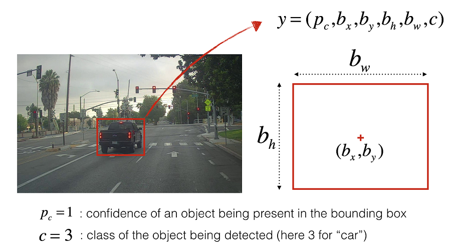
该函数可以在这里看到:
    def get_all_coordinates(self):
        '''
        This function takes no input and outputs the complete string with the coordinates
        of all the objects in view in the current image
        '''
        main_text_coordinates = '' # Initialize the variable where we'll store the coordinates
        for i, objct in enumerate(self.objects): # Loop through all of the objects
            print("     On object:", objct)
            b_box = self.find_bounding_box(objct) # Get current object's coordinates
            if b_box: # If find_bounding_box() doesn't return None
                print("         Initial coordinates:", b_box)
                text_coordinates = self.format_coordinates(b_box, i) # Reformat coordinates to YOLOv3 format
                print("         YOLO-friendly coordinates:", text_coordinates)
                main_text_coordinates = main_text_coordinates + text_coordinates # Update main_text_coordinates variables whith each
                                                                                 # line corresponding to each class in the frame of the current image
            else:
                print("         Object not visible")
                pass

        return main_text_coordinates # Return all coordinates
最后, main_text_coordinates以字符串形式返回。
9、数据生成获得的结果
运行以下代码,该代码调用 Render() 类,初始化相机端,然后启动数据生成循环。
## Run data generation
if __name__ == '__main__':
    # Initialize rendering class as r
    r = Render()
    # Initialize camera
    r.set_camera()
    # Begin data generation
    rotation_step = 5
    r.main_rendering_loop(rotation_step)
该程序会将进度输出到 Blender控制台窗口。 它将把图像和标签输出到指定位置。

如前所述,标签将具有以下格式。
0 <center_x> <center_y> <bounding_box_width> <bounding_box_height>
1 <center_x> <center_y> <bounding_box_width> <bounding_box_height>
2 <center_x> <center_y> <bounding_box_width> <bounding_box_height>
...
...
N_classes <center_x> <center_y> <bounding_box_width> <bounding_box_height>
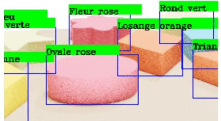
最后,我们运行一个程序,将输出的标签绘制到输出的图像上,以验证这些标签是否正确指向每个对象。
10、使用 YOLO 和 Google Colab 进行测试
我们决定使用YOLOv3的Darknet架构,并在Google Colab中实现。 我们从 AlexeyAB 的 Darknet 存储库下载了 darknet 架构。
本文重点介绍 YOLO 应用程序自动生成训练数据的过程,而不是训练本身,因此本节的目的是展示我们结果的简短摘要。
为了获得最佳性能,我们进行了 5 次不同的测试。 然而,受到自己计算机处理能力的极大限制,使用Nvidia GeForce MX150 GPU,渲染大约10000张图像最多需要一天半的时间。 这意味着创建大约 100000 张图像的数据集是不可行的,因为我们还需要将计算机用于其他目的。
无论如何,训练输出了以下损失图。

我们对结果进行了总结,发现如果不能表示测试中的变化,那么增加数据量并不总是有帮助。 这可以从测试 1 和测试 5 的比较中看出。

考虑到我们使用低容量计算机花了大约一周的时间来获取数据并训练我们的模型,识别结果是令人满意的。 这意味着合成数据生成的可扩展性非常好。 有了更好的资源,我们就可以用更多的数据来训练我们的算法,甚至更加逼真。
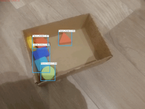
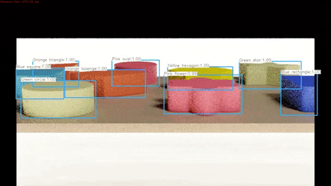
下面可以看到处理合成测试数据的算法的演示,完整的视频可以在此处 查看。
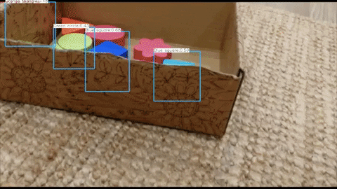
下面可以看到针对真实测试数据的算法演示,完整视频可以在此处 查看。
原文链接:Synthetic data generation for YOLO with Blender and Python
BimAnt翻译整理,转载请标明出处


