IfcCraneRailAShapeProfileDef
Definition
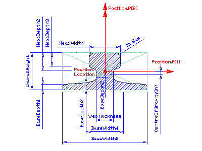
from IAI: The IfcCraneRailAShapeProfileDef
defines a section profile that provides the defining parameters of a
crane rail to be used by the swept area solid. Its parameters and
orientation relative to the position coordinate system are according to
the following illustration. The centre of the position coordinate
system is in the profiles centre
of the gravity bounding box.
The centre of gravity, if
given, is located in x direction within the center of the bounding box,
and in y-direction along the negative y axis, the offset value is given
by the offset parameter CentreOfGravityInY.
NOTE: This crane rail shape is
defined
according to DIN 536 (type A), but is used also in other locales.
HISTORY
New entity
in Release IFC2x Edition 2.
IFC2x
Edition 3 CHANGE All profile
origins are now in the center of the bounding box. The attribute CentreOfGravityInY
has been made
OPTIONAL. Upward compatibility for file based exchange is guaranteed.
Illustration:
 |
Position
The parameterized profile defines its own position coordinate system.
The underlying
coordinate system is defined by the swept area solid
that uses the profile definition. It is the xy plane of:
- IfcSweptAreaSolid.Position
by using offsets of the position location, the parameterized profile
can be positioned centric (using x,y offsets = 0.), or at any position
relative to the profile. Explicit coordinate offsets are used to define
cardinal points (e.g. upper-left bound).
Parameter
The parameterized profile
is defined by a set of parameter attributes, see attribute definition
below.
|
|
Table: Parameters of crane rail A shape
EXPRESS specification:
|
|
| ENTITY IfcCraneRailAShapeProfileDef
|
|
Attribute definitions:
| OverallHeight
|
:
|
Total extent of the height, defined parallel to the y axis of the position coordinate system. See illustration
above (= h1).
|
| BaseWidth2
|
:
|
Total extent of the width of the base, defined parallel to the x axis of the position coordinate system.
See illustration above (= b2).
|
| Radius
|
:
|
Edge radius according the above illustration (= r1).
|
| HeadWidth
|
:
|
Total extent of the width of the head, defined parallel to the x axis of the position coordinate system.
See illustration above (= b1).
|
| HeadDepth2
|
:
|
Head depth of the A shape crane rail, see illustration above (= h2).
|
| HeadDepth3
|
:
|
Head depth of the A shape crane rail, see illustration above (= h3).
|
| WebThickness
|
:
|
Thickness of the web of the A shape crane rail. See illustration above (= b3).
|
| BaseWidth4
|
:
|
Width of the base where thickness changes, defined parallel to the x axis of the position coordinate
system. See illustration above (= b4).
|
| BaseDepth1
|
:
|
Base depth of the A shape crane rail, see illustration above (= s1).
|
| BaseDepth2
|
:
|
Base depth of the A shape crane rail, see illustration above (= s2).
|
| BaseDepth3
|
:
|
Depth of the base where thickness changes, see illustration above (= s3).
|
| CentreOfGravityInY
|
:
|
Location of centre of gravity along the y axis measured from the center of the bounding box.
IFC2x Edition 2 Addendum 2 CHANGE The attribute CentreOfGravityInY has been made optional. Upward compatibility for file based exchange is guaranteed.
|
Inheritance graph
|
|
| ENTITY IfcCraneRailAShapeProfileDef;
|
|
