
NSDT工具推荐: Three.js AI纹理开发包 - YOLO合成数据生成器 - GLTF/GLB在线编辑 - 3D模型格式在线转换 - 可编程3D场景编辑器 - REVIT导出3D模型插件 - 3D模型语义搜索引擎 - AI模型在线查看 - Three.js虚拟轴心开发包 - 3D模型在线减面 - STL模型在线切割 - 3D道路快速建模
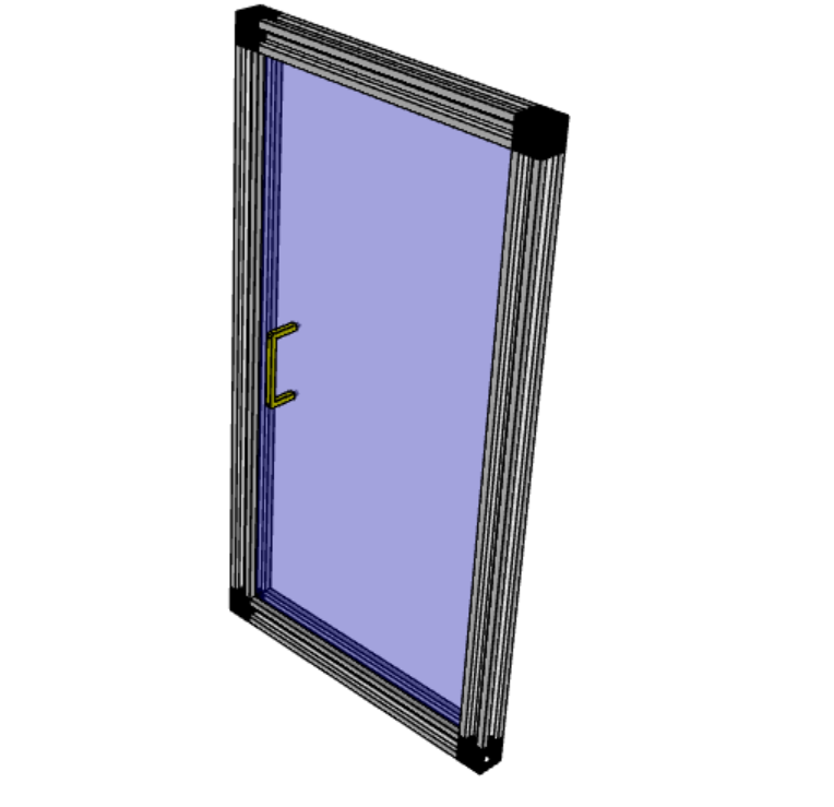
本教程介绍在CadQuery中如何使用装配约束功能来构建逼真的模型,我们将组装一个由 20x20 V 型槽型材制成的门组件。
1、定义参数
我们希望从定义模型参数开始,以便以后可以轻松更改尺寸:
import cadquery as cq

# Parameters
H = 400
W = 200
D = 350

PROFILE = cq.importers.importDXF("vslot-2020_1.dxf").wires()

SLOT_D = 5
PANEL_T = 3

HANDLE_D = 20
HANDLE_L = 50
HANDLE_W = 4
值得注意的是,v 槽轮廓是从 DXF 文件导入的。 这样就很容易更换为其他铝型材,例如博世或其他供应商提供的 DXF 文件。
2、定义可重用组件
接下来我们要定义根据指定参数生成装配组件的函数。
def make_vslot(l):

    return PROFILE.toPending().extrude(l)


def make_connector():

    rv = (
        cq.Workplane()
        .box(20, 20, 20)
        .faces("<X")
        .workplane()
        .cboreHole(6, 15, 18)
        .faces("<Z")
        .workplane(centerOption="CenterOfMass")
        .cboreHole(6, 15, 18)
    )

    # tag mating faces
    rv.faces(">X").tag("X").end()
    rv.faces(">Z").tag("Z").end()

    return rv


def make_panel(w, h, t, cutout):

    rv = (
        cq.Workplane("XZ")
        .rect(w, h)
        .extrude(t)
        .faces(">Y")
        .vertices()
        .rect(2*cutout,2*cutout)
        .cutThruAll()
        .faces("<Y")
        .workplane()
        .pushPoints([(-w / 3, HANDLE_L / 2), (-w / 3, -HANDLE_L / 2)])
        .hole(3)
    )

    # tag mating edges
    rv.faces(">Y").edges("%CIRCLE").edges(">Z").tag("hole1")
    rv.faces(">Y").edges("%CIRCLE").edges("<Z").tag("hole2")

    return rv


def make_handle(w, h, r):

    pts = ((0, 0), (w, 0), (w, h), (0, h))

    path = cq.Workplane().polyline(pts)

    rv = (
        cq.Workplane("YZ")
        .rect(r, r)
        .sweep(path, transition="round")
        .tag("solid")
        .faces("<X")
        .workplane()
        .faces("<X", tag="solid")
        .hole(r / 1.5)
    )

    # tag mating faces
    rv.faces("<X").faces(">Y").tag("mate1")
    rv.faces("<X").faces("<Y").tag("mate2")

    return rv
3、初始装配
接下来我们要实例化所有组件并将它们添加到组件中。
# define the elements
door = (
    cq.Assembly()
    .add(make_vslot(H), name="left")
    .add(make_vslot(H), name="right")
    .add(make_vslot(W), name="top")
    .add(make_vslot(W), name="bottom")
    .add(make_connector(), name="con_tl", color=cq.Color("black"))
    .add(make_connector(), name="con_tr", color=cq.Color("black"))
    .add(make_connector(), name="con_bl", color=cq.Color("black"))
    .add(make_connector(), name="con_br", color=cq.Color("black"))
    .add(
        make_panel(W + SLOT_D, H + SLOT_D, PANEL_T, SLOT_D),
        name="panel",
        color=cq.Color(0, 0, 1, 0.2),
    )
    .add(
        make_handle(HANDLE_D, HANDLE_L, HANDLE_W),
        name="handle",
        color=cq.Color("yellow"),
    )
)
4、约束定义
然后我们要定义所有的约束:
# define the constraints
(
    door
    # left profile
    .constrain("left@faces@<Z", "con_bl?Z", "Plane")
    .constrain("left@faces@<X", "con_bl?X", "Axis")
    .constrain("left@faces@>Z", "con_tl?Z", "Plane")
    .constrain("left@faces@<X", "con_tl?X", "Axis")
    # top
    .constrain("top@faces@<Z", "con_tl?X", "Plane")
    .constrain("top@faces@<Y", "con_tl@faces@>Y", "Axis")
    # bottom
    .constrain("bottom@faces@<Y", "con_bl@faces@>Y", "Axis")
    .constrain("bottom@faces@>Z", "con_bl?X", "Plane")
    # right connectors
    .constrain("top@faces@>Z", "con_tr@faces@>X", "Plane")
    .constrain("bottom@faces@<Z", "con_br@faces@>X", "Plane")
    .constrain("left@faces@>Z", "con_tr?Z", "Axis")
    .constrain("left@faces@<Z", "con_br?Z", "Axis")
    # right profile
    .constrain("right@faces@>Z", "con_tr@faces@>Z", "Plane")
    .constrain("right@faces@<X", "left@faces@<X", "Axis")
    # panel
    .constrain("left@faces@>X[-4]", "panel@faces@<X", "Plane")
    .constrain("left@faces@>Z", "panel@faces@>Z", "Axis")
    # handle
    .constrain("panel?hole1", "handle?mate1", "Plane")
    .constrain("panel?hole2", "handle?mate2", "Point")
)
如果你需要做一些基于字符串的选择器不可能做的不寻常的事情,例如使用 cadquery.selectors.BoxSelector 或用户定义的选择器类,可以直接将 cadquery.Shape 对象传递给 cadquery.Assembly.constrain( ) 方法。 例如,上面的
.constrain('part1@faces@>Z','part3@faces@<Z','Axis')等效于:
.constrain('part1',part1.faces('>z').val(),'part3',part3.faces('<Z').val(),'Axis')此方法需要一个 cadquery.Shape 对象,因此请记住使用 cadquery.Workplane.val() 方法传递单个 cadquery.Shape 而不是整个 cadquery.Workplane 对象。
5、最终结果
下面是完整的代码,包括最后的求解步骤。
import cadquery as cq

# Parameters
H = 400
W = 200
D = 350

PROFILE = cq.importers.importDXF("vslot-2020_1.dxf").wires()

SLOT_D = 6
PANEL_T = 3

HANDLE_D = 20
HANDLE_L = 50
HANDLE_W = 4


def make_vslot(l):

    return PROFILE.toPending().extrude(l)


def make_connector():

    rv = (
        cq.Workplane()
        .box(20, 20, 20)
        .faces("<X")
        .workplane()
        .cboreHole(6, 15, 18)
        .faces("<Z")
        .workplane(centerOption="CenterOfMass")
        .cboreHole(6, 15, 18)
    )

    # tag mating faces
    rv.faces(">X").tag("X").end()
    rv.faces(">Z").tag("Z").end()

    return rv


def make_panel(w, h, t, cutout):

    rv = (
        cq.Workplane("XZ")
        .rect(w, h)
        .extrude(t)
        .faces(">Y")
        .vertices()
        .rect(2*cutout,2*cutout)
        .cutThruAll()
        .faces("<Y")
        .workplane()
        .pushPoints([(-w / 3, HANDLE_L / 2), (-w / 3, -HANDLE_L / 2)])
        .hole(3)
    )

    # tag mating edges
    rv.faces(">Y").edges("%CIRCLE").edges(">Z").tag("hole1")
    rv.faces(">Y").edges("%CIRCLE").edges("<Z").tag("hole2")

    return rv


def make_handle(w, h, r):

    pts = ((0, 0), (w, 0), (w, h), (0, h))

    path = cq.Workplane().polyline(pts)

    rv = (
        cq.Workplane("YZ")
        .rect(r, r)
        .sweep(path, transition="round")
        .tag("solid")
        .faces("<X")
        .workplane()
        .faces("<X", tag="solid")
        .hole(r / 1.5)
    )

    # tag mating faces
    rv.faces("<X").faces(">Y").tag("mate1")
    rv.faces("<X").faces("<Y").tag("mate2")

    return rv


# define the elements
door = (
    cq.Assembly()
    .add(make_vslot(H), name="left")
    .add(make_vslot(H), name="right")
    .add(make_vslot(W), name="top")
    .add(make_vslot(W), name="bottom")
    .add(make_connector(), name="con_tl", color=cq.Color("black"))
    .add(make_connector(), name="con_tr", color=cq.Color("black"))
    .add(make_connector(), name="con_bl", color=cq.Color("black"))
    .add(make_connector(), name="con_br", color=cq.Color("black"))
    .add(
        make_panel(W + 2*SLOT_D, H + 2*SLOT_D, PANEL_T, SLOT_D),
        name="panel",
        color=cq.Color(0, 0, 1, 0.2),
    )
    .add(
        make_handle(HANDLE_D, HANDLE_L, HANDLE_W),
        name="handle",
        color=cq.Color("yellow"),
    )
)

# define the constraints
(
    door
    # left profile
    .constrain("left@faces@<Z", "con_bl?Z", "Plane")
    .constrain("left@faces@<X", "con_bl?X", "Axis")
    .constrain("left@faces@>Z", "con_tl?Z", "Plane")
    .constrain("left@faces@<X", "con_tl?X", "Axis")
    # top
    .constrain("top@faces@<Z", "con_tl?X", "Plane")
    .constrain("top@faces@<Y", "con_tl@faces@>Y", "Axis")
    # bottom
    .constrain("bottom@faces@<Y", "con_bl@faces@>Y", "Axis")
    .constrain("bottom@faces@>Z", "con_bl?X", "Plane")
    # right connectors
    .constrain("top@faces@>Z", "con_tr@faces@>X", "Plane")
    .constrain("bottom@faces@<Z", "con_br@faces@>X", "Plane")
    .constrain("left@faces@>Z", "con_tr?Z", "Axis")
    .constrain("left@faces@<Z", "con_br?Z", "Axis")
    # right profile
    .constrain("right@faces@>Z", "con_tr@faces@>Z", "Plane")
    .constrain("right@faces@<X", "left@faces@<X", "Axis")
    # panel
    .constrain("left@faces@>X[-4]", "panel@faces@<X", "Plane")
    .constrain("left@faces@>Z", "panel@faces@>Z", "Axis")
    # handle
    .constrain("panel?hole1", "handle?mate1", "Plane")
    .constrain("panel?hole2", "handle?mate2", "Point")
)

# solve
door.solve()

show_object(door,name='door')
6、数据导出
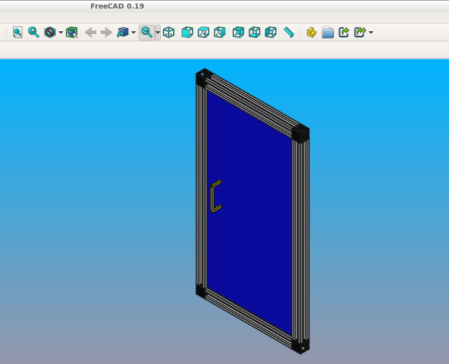
生成的程序集可以导出为 STEP 文件或内部 OCCT XML 格式。
STEP 可以加载到所有 CAD 工具中,例如在 FreeCAD 中,XML 可用于其他使用 OCCT 的应用程序。
 door.save('door.step')
 door.save('door.xml')
当保存为STEP格式时,颜色被保留但不透明。
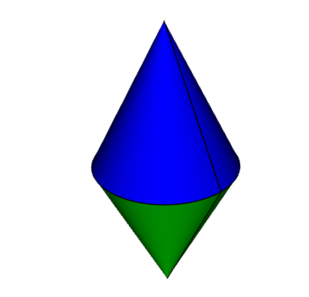
7、对象位置
可以将对象添加到具有提供的初始位置的装配中,例如:
import cadquery as cq

cone = cq.Solid.makeCone(1, 0, 2)

assy = cq.Assembly()
assy.add(
    cone,
    loc=cq.Location(cq.Vector(0, 0, 0), cq.Vector(1, 0, 0), 180),
    name="cone0",
    color=cq.Color("green")
)
assy.add(cone, name="cone1", color=cq.Color("blue"))

show_object(assy)
作为用户计算位置的替代方法,约束的 solve() 方法可用于在装配结果中定位对象。
如果同时使用初始位置和 solve() 方法,求解器将用它的解覆盖这些初始位置,但是初始位置仍然会影响最终解。 在欠约束系统中,如果对象对成本函数没有贡献,或者如果存在多个解决方案(即成本函数最小的多个实例),求解器可能不会移动对象,初始位置可能导致求解器收敛于一个特定的解决方案。 对于非常复杂的组件,设置近似正确的初始位置也可以减少所需的计算时间。
8、约束
约束通常比直接提供位置更好地表示用户想要建模的现实世界关系。 在上面的例子中,真实世界的关系是每个圆锥体的底面应该接触,这可以用平面约束建模。 当用户提供明确的位置(而不是约束)时,也会进行更新,例如,当 cone1 的位置发生变化时。
当至少提供一个约束并运行方法 solve() 时,就定义了一个优化问题。 每个约束都提供一个成本函数,该函数取决于创建约束时指定的两个对象的位置和方向(由 Location 表示)。 解算器改变装配子项的位置并尝试最小化所有成本函数的总和。 因此,通过阅读下面的成本函数公式,你可以准确理解每个约束的作用。
9、点约束
点约束是一种经常使用的约束,它可以最小化两点之间的距离。 一些示例用途是居中面或对齐顶点,但它也可用于虚拟顶点以在两个部件之间创建偏移。
成本函数是:
其中:
param是约束的参数,默认为0,ci是第 i 个对象的中心,并且|vi|是vi的模,即其长度
创建点约束时, param 参数可用于指定两个中心之间的所需偏移量。 这个偏移量没有与之关联的方向,如果你想指定一个特定方向的偏移量,那么你应该使用一个虚拟顶点。
点约束使用 Center() 来查找参数的中心。 因此它适用于 Shape 的所有子类。
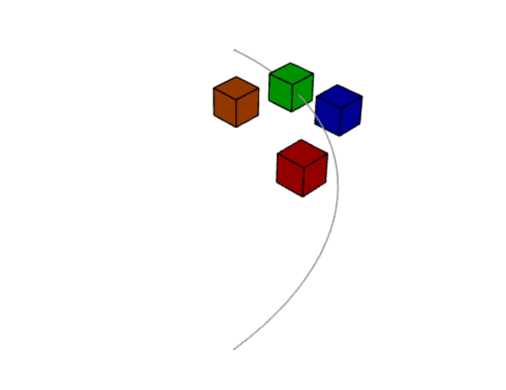
import cadquery as cq

# Use the Point constraint to position boxes relative to an arc
line = cq.Edge.makeCircle(radius=10, angle1=0, angle2=90)
box = cq.Workplane().box(1, 1, 1)

assy = cq.Assembly()
assy.add(line, name="line")

# position the red box on the center of the arc
assy.add(box, name="box0", color=cq.Color("red"))
assy.constrain("line", "box0", "Point")

# position the green box at a normalized distance of 0.8 along the arc
position0 = line.positionAt(0.8)
assy.add(box, name="box1", color=cq.Color("green"))
assy.constrain(
    "line", cq.Vertex.makeVertex(*position0.toTuple()), "box1", box.val(), "Point",
)

# position the orange box 2 units in any direction from the green box
assy.add(box, name="box2", color=cq.Color("orange"))
assy.constrain(
    "line",
    cq.Vertex.makeVertex(*position0.toTuple()),
    "box2",
    box.val(),
    "Point",
    param=2,
)

# position the blue box offset 2 units in the x direction from the green box
position1 = position0 + cq.Vector(2, 0, 0)
assy.add(box, name="box3", color=cq.Color("blue"))
assy.constrain(
    "line", cq.Vertex.makeVertex(*position1.toTuple()), "box3", box.val(), "Point",
)

assy.solve()
show_object(assy)
10、轴约束
轴约束最小化两个向量之间的角度。 它经常用于对齐面和控制对象的旋转。
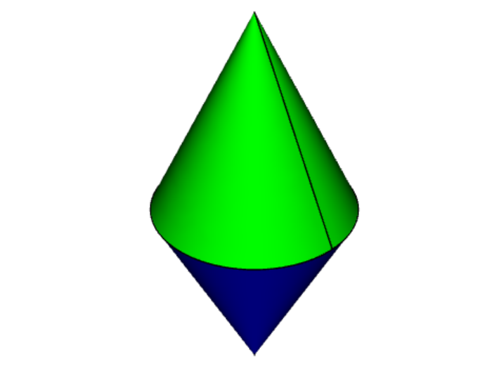
成本函数是:
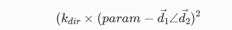
其中:
kdir是方向约束的比例因子,param是约束的参数,默认为弧度,di是从第 i 个对象参数创建的方向,如下所述,并且d1<d2是d1和d2之间的弧度角
参数 param默认为π弧度,它将两个方向设置为彼此相反。 这代表了通常所说的“配对”关系,即两个物体的外表面接触。
import cadquery as cq

cone = cq.Solid.makeCone(1, 0, 2)

assy = cq.Assembly()
assy.add(cone, name="cone0", color=cq.Color("green"))
assy.add(cone, name="cone1", color=cq.Color("blue"))
assy.constrain("cone0@faces@<Z", "cone1@faces@<Z", "Axis")

assy.solve()
show_object(assy)
如果 param 参数设置为零,则两个对象将指向同一方向。 这通常在一个物体穿过另一个物体时使用,例如一根钉进入板上的孔:
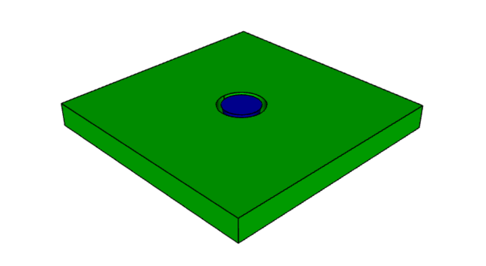
import cadquery as cq

plate = cq.Workplane().box(10, 10, 1).faces(">Z").workplane().hole(2)
cone = cq.Solid.makeCone(0.8, 0, 4)

assy = cq.Assembly()
assy.add(plate, name="plate", color=cq.Color("green"))
assy.add(cone, name="cone", color=cq.Color("blue"))
# place the center of the flat face of the cone in the center of the upper face of the plate
assy.constrain("plate@faces@>Z", "cone@faces@<Z", "Point")

# set both the flat face of the cone and the upper face of the plate to point in the same direction
assy.constrain("plate@faces@>Z", "cone@faces@<Z", "Axis", param=0)

assy.solve()
show_object(assy)
在创建轴约束时,将根据对象的类型以三种不同方式之一提取方向矢量:
- 面:使用
normalAt() - Edge 和
geomType()是“CIRCLE”:使用normal() - Edge 和
geomType()不是“CIRCLE”:使用tangentAt()
使用任何其他类型的对象都会引发 ValueError。 到目前为止,最常见的用例是从面定义轴约束。
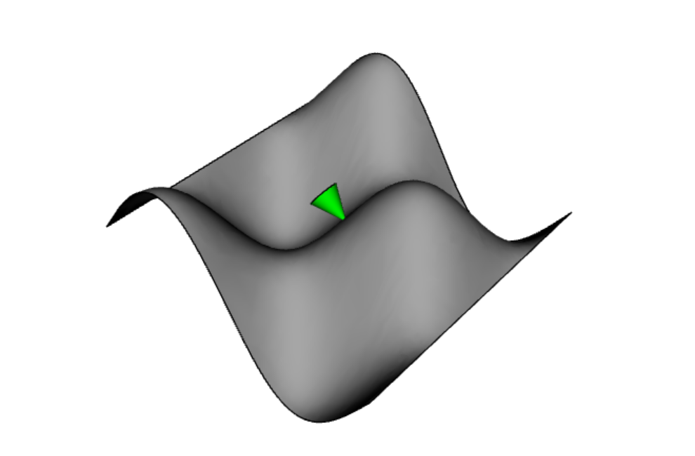
import cadquery as cq
from math import cos, sin, pi

# Create a sinusoidal surface:
surf = cq.Workplane().parametricSurface(
    lambda u, v: (u, v, 5 * sin(pi * u / 10) * cos(pi * v / 10)),
    N=40,
    start=0,
    stop=20,
)

# Create a cone with a small, flat tip:
cone = (
    cq.Workplane()
    .add(cq.Solid.makeCone(1, 0.1, 2))
    # tag the tip for easy reference in the constraint:
    .faces(">Z")
    .tag("tip")
    .end()
)

assy = cq.Assembly()
assy.add(surf, name="surf", color=cq.Color("lightgray"))
assy.add(cone, name="cone", color=cq.Color("green"))
# set the Face on the tip of the cone to point in
# the opposite direction of the center of the surface:
assy.constrain("surf", "cone?tip", "Axis")
# to make the example clearer, move the cone to the center of the face:
assy.constrain("surf", "cone?tip", "Point")
assy.solve()

show_object(assy)
11、平面约束
平面约束只是 点约束和 轴约束的组合。 它是常用约束组合的便捷快捷方式。 它可用于将前面的示例从两个约束缩短为一个:
assy = cq.Assembly()
assy.add(surf, name="surf", color=cq.Color("lightgray"))
assy.add(cone, name="cone", color=cq.Color("green"))
-# set the Face on the tip of the cone to point in
-# the opposite direction of the center of the surface:
-assy.constrain("surf", "cone?tip", "Axis")
-# to make the example clearer, move the cone to the center of the face:
-assy.constrain("surf", "cone?tip", "Point")
+assy.constrain("surf", "cone?tip", "Plane")
assy.solve()

show_object(assy)
此代码的结果与上述两个约束示例相同。
面约束的成本函数,请参见 点约束 和 轴约束 部分。 param 参数应用于 Axis 并且应该保留为“mate”样式约束(两个表面接触)的默认值,或者可以设置为 0 用于通过表面约束(参见 轴约束部分中的描述)。
12、点平面约束
点平面约束将第一个对象的中心定位在第二个对象定义的平面内。 成本函数是:
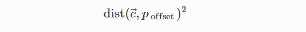
其中:
c是第一个对象的中心,poffset是从第二个对象创建的平面,在平面的法线方向上偏移param参数,并且dist(a,b)是点a和 平面b之间的距离
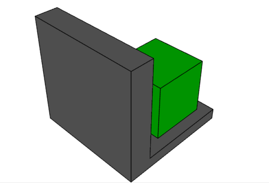
import cadquery as cq

# Create an L-shaped object:
bracket = (
    cq.Workplane("YZ")
    .hLine(1)
    .vLine(0.1)
    .hLineTo(0.2)
    .vLineTo(1)
    .hLineTo(0)
    .close()
    .extrude(1)
    # tag some faces for easy reference:
    .faces(">Y[1]")
    .tag("inner_vert")
    .end()
    .faces(">Z[1]")
    .tag("inner_horiz")
    .end()
)

box = cq.Workplane().box(0.5, 0.5, 0.5)

assy = cq.Assembly()
assy.add(bracket, name="bracket", color=cq.Color("gray"))
assy.add(box, name="box", color=cq.Color("green"))

# lock bracket orientation:
assy.constrain("bracket@faces@>Z", "box@faces@>Z", "Axis", param=0)
assy.constrain("bracket@faces@>X", "box@faces@>X", "Axis", param=0)

# constrain the bottom of the box to be on the plane defined by inner_horiz:
assy.constrain("box@faces@<Z", "bracket?inner_horiz", "PointInPlane")
# constrain the side of the box to be 0.2 units from the plane defined by inner_vert
assy.constrain("box@faces@<Y", "bracket?inner_vert", "PointInPlane", param=0.2)
# constrain the end of the box to be 0.1 units inside the end of the bracket
assy.constrain("box@faces@>X", "bracket@faces@>X", "PointInPlane", param=-0.1)

assy.solve()
show_object(assy)
13、点线约束
点线约束将第一个对象的中心定位在第二个对象定义的线上。 成本函数是:
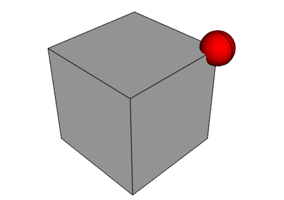
其中:
c是第一个参数的中心,l是从第二个对象创建的一条线param是约束的参数,默认为0,dist(a,b)是点a和线l之间的距离
import cadquery as cq
b1 = cq.Workplane().box(1,1,1)
b2 = cq.Workplane().sphere(0.15)
assy = (
cq.Assembly()
.add(b1,name='b1')
.add(b2, loc=cq.Location(cq.Vector(0,0,4)), name='b2', color=cq.Color('red'))
)
# fix the position of b1
assy.constrain('b1','Fixed')
# b2 on one of the edges of b1
assy.constrain('b2','b1@edges@>>Z and >>Y','PointOnLine')
# b2 on another of the edges of b1
assy.constrain('b2','b1@edges@>>Z and >>X','PointOnLine')
# effectively b2 will be constrained to be on the intersection of the two edges
assy.solve()
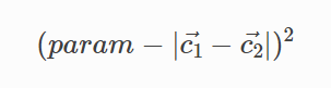
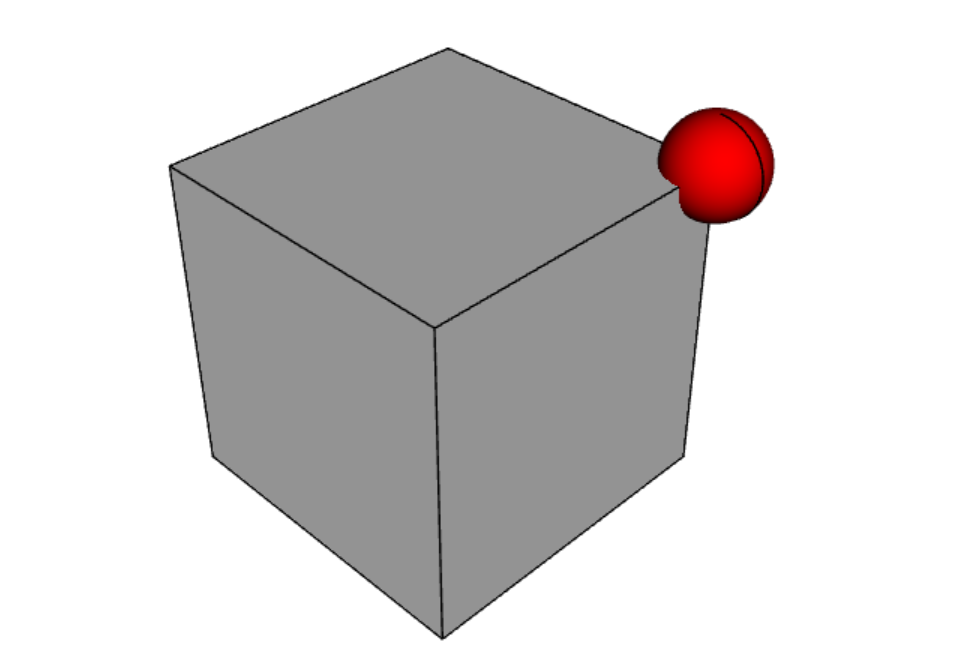
show_object(assy)14、固定点约束
固定点约束将给定参数的位置固定为等于通过约束参数指定的给定点。 此约束锁定参数的所有平移自由度。 成本函数是:
其中:
c是对象的中心,param是约束参数 - 指定目标位置的元组,dist(a,b)是点a和线l之间的距离
import cadquery as cq
b1 = cq.Workplane().box(1,1,1)
b2 = cq.Workplane().sphere(0.15)
assy = (
cq.Assembly()
.add(b1,name='b1')
.add(b2, loc=cq.Location(cq.Vector(0,0,4)), name='b2', color=cq.Color('red'))
)
# fix the position of b1
assy.constrain('b1','Fixed')
# b2 on one of the edges of b1
assy.constrain('b2','b1@edges@>>Z and >>Y','PointOnLine')
# b2 on another of the edges of b1
assy.constrain('b2','b1@edges@>>Z and >>X','PointOnLine')
# effectively b2 will be constrained to be on the intersection of the two edges
assy.solve()
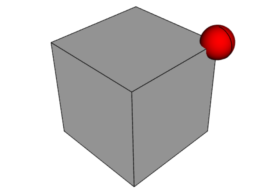
show_object(assy)15、固定旋转约束
固定旋转约束将给定对象的旋转固定为等于通过约束参数指定的值。 对象首先绕原点旋转 Z 角,然后是 Y,最后是 X。
该约束锁定对象的所有旋转自由度。 成本函数是:
其中:
R向量应用于对象的旋转角度param是约束参数 - 指定目标旋转的元组。

import cadquery as cq
b1 = cq.Workplane().box(1,1,1)
b2 = cq.Workplane().rect(0.1, 0.1).extrude(1,taper=-15)
assy = (
cq.Assembly()
.add(b1,name='b1')
.add(b2, loc=cq.Location(cq.Vector(0,0,4)), name='b2', color=cq.Color('red'))
)
# fix the position of b1
assy.constrain('b1','Fixed')
# fix b2 bottom face position (but not rotation)
assy.constrain('b2@faces@<Z','FixedPoint',(0,0,0.5))
# fix b2 rotational degrees of freedom too
assy.constrain('b2','FixedRotation',(45,0,45))
assy.solve()
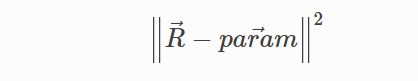
show_object(assy)16、固定轴约束
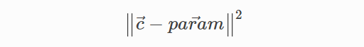
固定轴约束将给定参数的法线或切线的方向固定为等于通过约束参数指定的矢量的方向。 此约束锁定参数的两个旋转自由度。 成本函数是:
其中:
a表示对象的法向量或切向量,param是约束的参数 - 指定目标方向的元组。
import cadquery as cq

b1 = cq.Workplane().box(1,1,1)
b2 = cq.Workplane().rect(0.1, 0.1).extrude(1,taper=-15)

assy = (
    cq.Assembly()
    .add(b1,name='b1')
    .add(b2, loc=cq.Location(cq.Vector(0,0,4)), name='b2', color=cq.Color('red'))
)

# fix the position of b1
assy.constrain('b1','Fixed')
# fix b2 bottom face position (but not rotation)
assy.constrain('b2@faces@<Z','FixedPoint',(0,0,0.5))
# fix b2 some rotational degrees of freedom too
assy.constrain('b2@faces@>Z','FixedAxis',(1,0,2))

assy.solve()
show_object(assy)原文链接:Assembly tutorial - CadQuery
BimAnt翻译整理,转载请标明出处


